Composite Manufacturing
Tubes, Plates, Shells n’ stuff
Due to my hobby of high power rocketry, specifically of a higher performance blend, making composite aerostructures got me into composite manufacturing and analysis. As a result, I’ve worked on more composite manufacturing, mostly for rocketry purposes. In addition, as a Purdue University student, I have take comprehensive composites characterization and manufacturing courses as the state of the art Composite Manufacturing and Simulation Center (CMSC).
Composite Tubes
Composite tubes were the first parts I made. This process consists of using a tubular mandrel and sheet-based mylar release film. From there, I used one of two methods. The first was roll wrapping, involving rolling a sheet of woven fabric around the tube, primarily for body tubes and fincans. The second method uses biaxial sleeving, primarily made for pressure vessels. These processes are currently all wet layup, so most volume fractions are around Vf = 0.4-0.5. Adding compression to these processes is the next step and upgrading to prepreg and elevated temperature processes.
The roll-wrapping process with the setup (left), the rolled layup (middle), and the trimmed and sanded final tube, to be used for a rocket fincan.
Nosecone Molding
Current methods for making custom composite rocket nosecones in the high-power rocketry communities follow 2 general schools of thought, in two aspects. The first is the type of molding process: 2 part negative molding, and plug molding, and the second is the type of reinforcement: composite fabrics, and composite biaxial sleeving.
Plug molding uses a mold whose outer mold line(OML) matches the inner mold line(IML) of the molded part. This is a simple process, that involves a mold that is a single body, and can use a variety of reinforcements. The resulting parts have high dimensional accuracy with respect to the IML of the produced parts, but the OML of said parts is prone to print through and roughness, often requiring extensive post-processing. The second method is a negative multi-part molding process. In this case, generally the negative formed by the mold parts, that is the IML formed by the mold, matches the OML of the molded part. Often these molds are two-part, in halves.
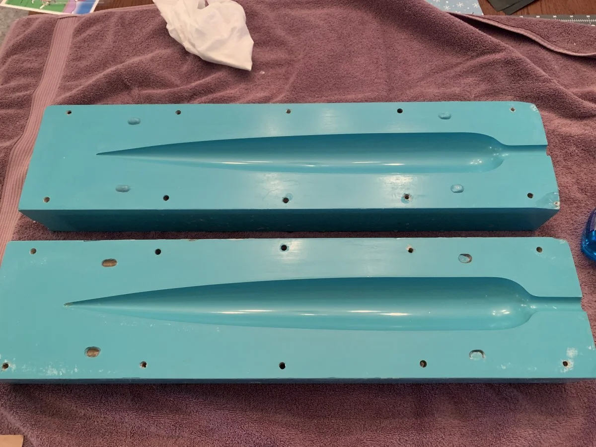
Female nosecone mold, used in conjunction with a pressurized bladder (left). Nosecone plug mold, no additional consolidation used (right).
The first type of reinforcement is composite fabrics, such as woven and unidirectional carbon fiber, fiberglass, kevlar, and more. These fabrics make efficient use of the fiber and allow for the most optimized layup and reinforcement of the composite parts. They are commonly used with negative molds, but can also be used with plug molds. This method often involves a lot of preparation for the plies, as the fabric cannot be continuous around the circumference of the parts. When the surface is unwrapped and cut into plies, these plies are called gores.
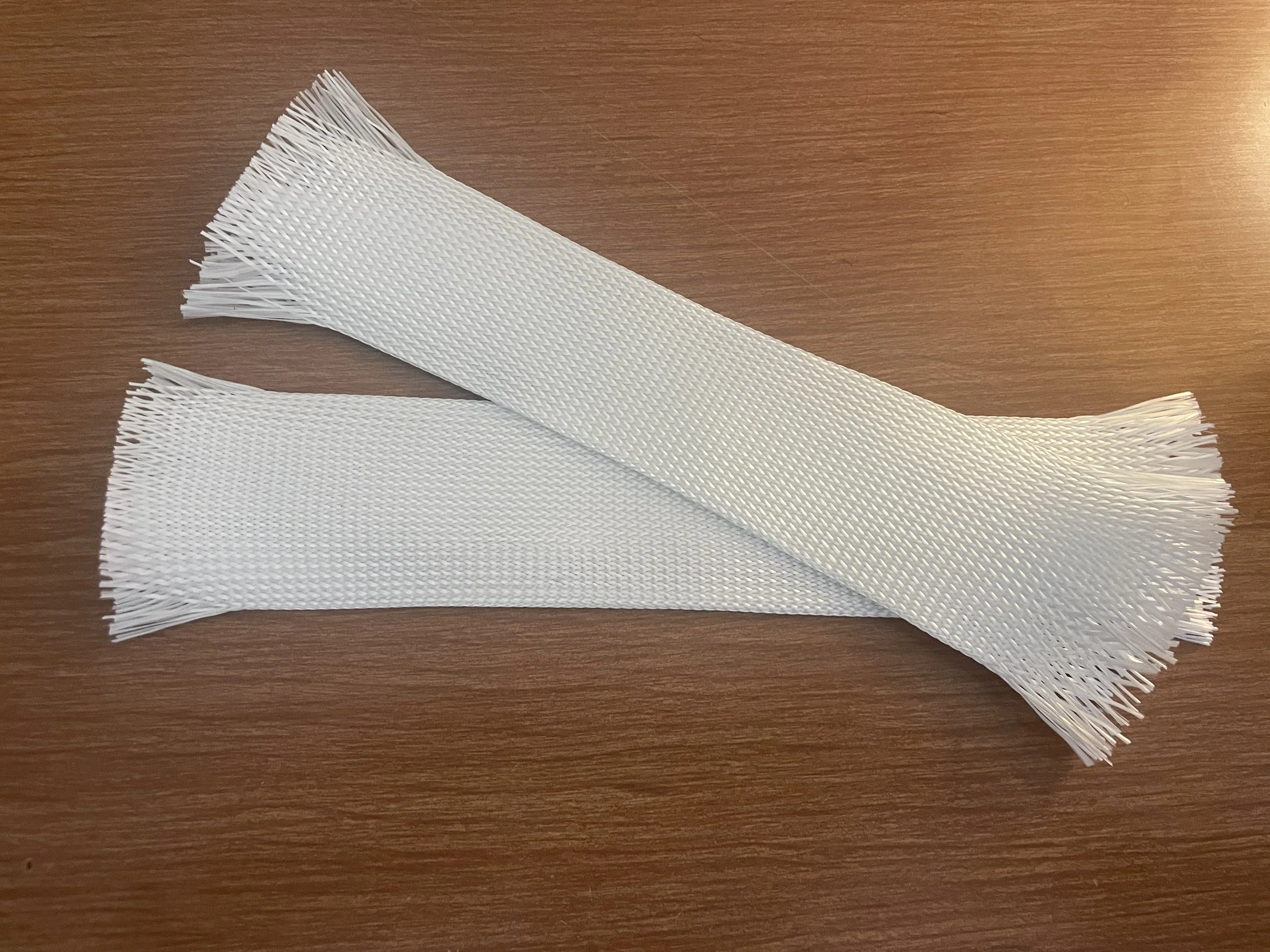
Hexcel AS4 3k plain weave carbon fiber fabric (left). Fiberglass 2.75” 3k biaxial sleeving (right).
The second type of reinforcement is composite biaxial sleeving. This sleeve is a woven fabric, with fiber in two directions, hence biaxial. This reinforcement expands in diameter when axially compressed, and shrinks in diameter when axially stretched, like a Chinese finger trap. This makes it quite easy to make parts with circular cross-sections along one axis, like a nosecone, and allows for more complex nosecone geometries(Von Karman, Power Series, Ogive, etc.).
When both of these factors are combined, there most common configurations are as follows: plug molding with biaxial sleeves, and negative molding with gores. The former is by far the most common method, with most hobbiests achieving a smooth IML while sacrificing the OML finish out of the mold. Further processing would be required to finish the OML, including steps such as filling, sanding, and painting.
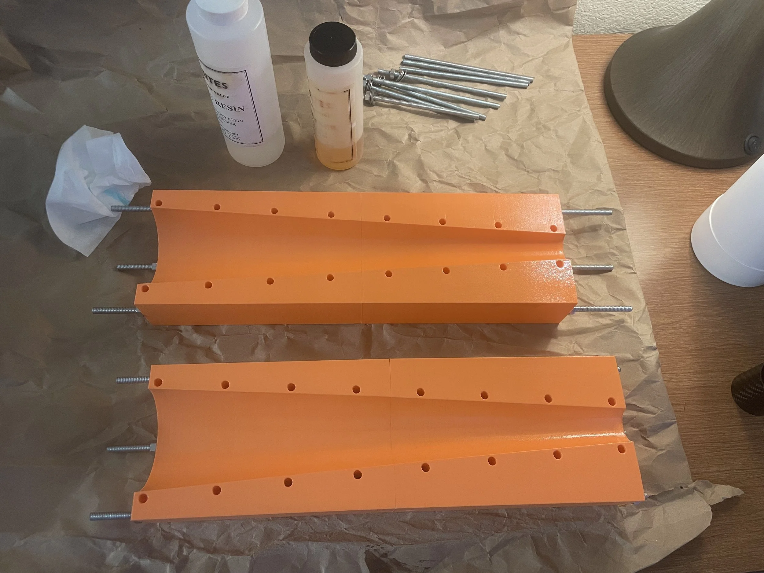
However, a third option is a combination of the two modling methods, with a negative and positive 3 piece mold. This process does require more up front investment in tme, or capital. I decided to explore the former option, and 3D printed all the tooling necessary for making 54mm conical nosecones, a standard diameter in high power rocketry. The negative halves were each printed in two halves that get bolted together. The tool surfaces were sanded, coated with epoxy, and then sanded again. Similarly, the plug mold was printed in two halves and molted together axially.
Sanded negative mold halves prior to epoxy coating of tool surface (left). Negative mold halves post coating (right).
All mold parts sanded, and ready to be used to make nosecones.
Cured nosecone prior to demolding (left). Cured nosecone after demolding and trimming (right).
The test nosecone had a good degree of dimensional accuracy on the ID and fairly good dimensional accuracy on the OD. However, the wall thickness varies slightly. The next step to remedy this is to use spacers above and below the layup to establish a net section thickness, and then use compression to force the part to conform to such a thickness.


