Composite Design and Analysis
While my first introduction to composite materials was in their manufacturing and processing, I soon became curious about the strength of the materials I was making. Due to a desire to determine how stiff and strong my structures were, I delved into the realm of material properties predictions and structural analysis. In my exploration, I have learned many new concepts, such as rule of mixtures, laminate plate theory, static linear FEA (Ansys), and buckling. In addition, my interest in composites led me to collegiate coursework in mechanics of composite materials, and characterization of composite materials, the latter of which happened under Professor R. Byron Pipes, the head of the Composites Manufacturing and Simulations Center at Purdue University.
Loads Determination, Laminate Plate Theory, and Structural Analysis
Description - RASP
My first interest was to create an integrated loads and structural analysis tool for rockets with composite aerostructures. The general framework was to obtain the mass and dimensions of the parts of the rocket and build a sort of digital twin of the rocket. Due to the highly axisymmetric nature of rockets, the geometric model was 1 dimensional. This, along with information about the flight regime of the rocket taken from OpenRocket (an open-source rocket trajectory simulation program) was then used to calculate the axial and transverse/bending loads on the rocket. These applied loads were used to do structural analysis of large, general portions of the rocket, including the nosecone, and the airframe. The name stands for Rocket Structural Analytical Program, more for fun than any actual legitimate meaning.
Current Model Functionality
The most recent version of this script is written in MATLAB, and does the following: Builds a mass & geometric digital twin, calculates aerodynamic forces acting on the rocket, calculates material properties of a given composite material & layup, and performs structural analysis on the individual components of the rocket.
Mass & Geometric Model
First, the “main” contains all geometric and internal inputs required to construct a geometric and mass model of the rocket. The aerostructures have associated dimensions to fully describe the 3D shapes, while the internals are modeled as point masses. Initially, this was done with each component as its own class, but this proved difficult to implement, and defining the scope for each of these was difficult.
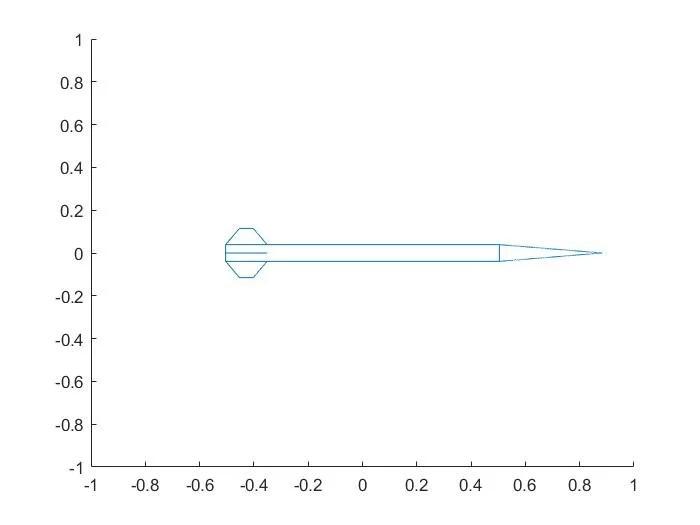
Basic geometric rocket display from the script, displaying the profile of my custom carbon fiber L1 rocket.
Aerodynamic Loads Determination
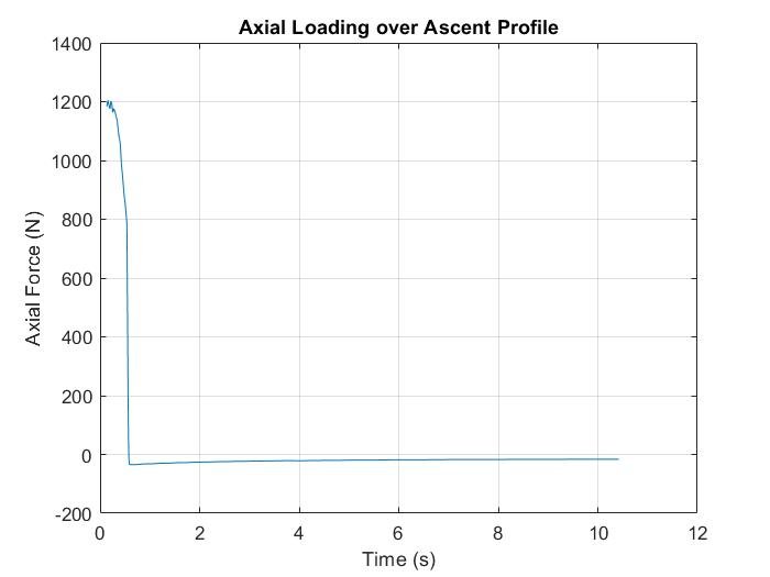
Second, a script calculates the aerodynamic loads acting on the rocket based on the aerodynamic inputs from OpenRocket. These are split into two general categories, the axial load from acceleration, drag, and thrust, and the transverse/bending load due to an angle of attack (AoA). The loads are calculated as functions of time, as OpenRocket can give all outputs as functions of time. Specifically, the domain of interest is during boost, or when the motor is burning, as the MaxQ for small, solid-fuel rockets as these often occurs right at burnout.
Axial Load:
The axial load has three components for its calculation. The first is thrust, pushing against the base of the rocket, where the thrust is transferred to the airframe. The inertial load and vertical drag are additive, as they both act to push the rocket “downwards” acting in the opposite direction to motion. Now the question becomes how to resolve these forces in opposing “directions”. In classical beam theory, the simplest method to analyze the rocket is as a fixed free, or simply supported beam. In the physical world, a force with no opposite does not create any deformation on a free moving object, in this case the rocket. There must be a pair of forces, one to react the other. The lower of the two forces is taken, as that is the maximum force that can be reacted by the pair.
Transverse Load:
The method for calculating the transverse load is much simpler. First, the aerodynamic moments are balanced around the center of pressure (CP). As a result, this means that the aft section of the rocket can be ignored, and complex aerodynamic interactions between the fins and the body can be abstracted away. At a given AoA, the formula for the side force is: Q*sin(AoA)*A, where Q is the dynamic pressure, sin(AoA) is present to capture the horizontal component of the force, and A is the projected area of the forebody (airframe & nosecone forward of the CP).
Axial load vs. time (left), and transverse/shear force and bending moment vs. time (right) for my custom carbon fiber L1 certification rocket.
Composite Laminate Properties Determination
The third component of the tool takes the properties of a composite as inputs. These include fiber volume fraction (Vf), number of plies, ply thickness, stacking sequence, fiber properties, and matrix properties. From these, the script calculates the effective properties of the laminate using classical laminate plate theory. These properties can be specified to be for a woven or unidirectional laminate. It also estimates strength characteristics using an empirical scaling approach with a set of reference properties. This method compares the calculates E1 of the lamina to a reference at known Vf. A scaling factor is then applied to the reference lamina strengths and used in a thickness average to determine the laminate strengths.
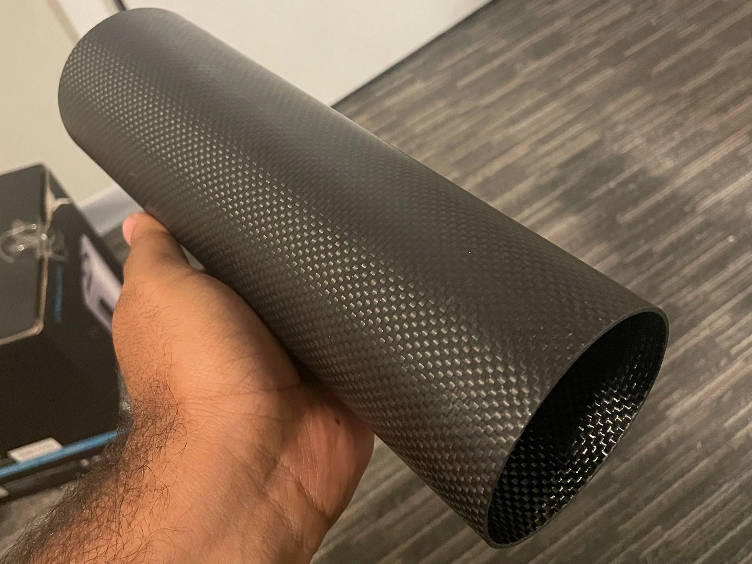
Future steps involve mechanical testing to verify laminate moduli and strength characteristics, as well as ply failure models for more complex laminates. Currently, most airframes are made from woven roll-wrapped reinforcement, modeled as n 0/90 woven plies, where n is the number of circumferential wraps. Custom nosecones are often made from biaxial sleeving, which has restrictions around determining stacking sequence, and non-constant fiber angles along its length.
Structural Analysis
The structural analysis currently focuses on the buckling/bending of airframes and buckling of nosecones. Future work will include basic FE methods for bending of nosecones, as well as more information of aerodynamic flutter of fins, and potentially bending of fins, although this is generally not a failure mode in flight. All structures are either modeled as fixed-free or imply supported structures.
Example output of the structural analysis of RASP, for a short MD 3” rocket (Airframe dimensions: 2.965” ID, 3.095” OD, and 10” length)(left), the as manufactured airframe(right).
Analytical methods for the buckling of airframes due to axial loads are explored in the form of the classical, semi-empirical Euler method for slender columns, supplemented by the Johnson-Parabola method for intermediate cylinders. A clear limitation of this method is that it is intended for linear isotropic materials, and while the composites often used in rocketry exhibit linear behavior, they are orthotropic at best. In many cases, with woven plies all in the same 0/90 orientation, the laminate is similarly orthotopic. In order to mitigate this, an analytical method for ring-and-stringer stiffened orthotropic cylinders, presented in NASA SP-8007, and is implemented for an unstiffened cylinder in the script. Both criterion are calculated, but the Euler/Johnson is only used as a second reference point.
Similarly, bending failure modes are explored. The first is if the airframe bends to the point where the bending stress exceeds the material limits. The second criteria is based on the brazier buckling effect. This is buckling induced by a reduction in second moment of area, which is in turn caused by deformation. It is also known as “kinking”. The third method is a NASA method published in AIAA. It uses analytical methods to calculate the critical bending moment, and compares the applied bending strain to the critical bending strain.
The nosecone analysis utilizes a method presented in NASA SP-8009 for the buckling load of truncated conical shells.
In addition the analytical methods used, finite element analysis (FEA) was used to investigate the buckling failure of the airframe. This was mainly pursued to gain experience in running component-level FEA, even simple linear analyses, using custom materials, loads, and geometries. However, buckling can be a significantly non-linear behavior, and my skills have not progressed to the point of being able to perform such analyses, meaning that the failure I am investigating with the FEA is likely not the limiting case.


